Understanding Earthing: Ensuring Electrical Safety
Understanding Earthing: Ensuring Electrical Safety
Why Earthing Systems Matter More Than You 🤔
What Is Earthing?🤔

Earthing, also known as grounding.Earthing is achieved by connecting the non-current-carrying parts of equipment, or the neutral point of a power system, to the ground using low-resistance materials such as copper or galvanized iron (GI) wire. This ensures that any leakage current flows safely into the ground, rather than through the human body or equipment casing.
Types of Earthing:
1. System Earthing:
Involves earthing current-carrying conductors.Ensures system security.
2. Equipment Earthing:
Involves earthing non-current carrying parts.Protects humans, animals, and property.
Key Points That Must Be Earthed
To ensure optimal safety and system performance, the following items must be earthed:
Plug Sockets: Earth pins in 3-pin and 4-pin plug sockets must be permanently earthed.
Metallic Casings: This includes all metal parts of appliances like GI pipes, fan rods, transformers, motors, etc.
Medium Voltage Equipment: Must be earthed at two separate, distinct points.
Neutral Conductors: In three-phase and 2-phase systems, neutral wires should have at least two distinct earthing points.
DC Systems: The middle wire must be earthed at the generating station.
Earth Wires Along Distribution Lines: Should be earthed at intervals of at least every 1.6 km with four equally spaced points.
Stay Wires: Used in overhead lines, they must also be earthed.
Components of an Earthing System
An effective earthing system consists of:
Earth Electrode: A buried conductor (copper, galvanized iron, or cast iron) that facilitates grounding.
Earth Continuity Conductor (ECC): Connects the distribution board to various appliances.
Earth Lead: Links the ECC with the earth electrode.
Understanding Earth Resistance
Earth resistance refers to the resistance between the earth and the electrode. It affects how efficiently the current is discharged into the ground. It's measured using a tool called an Earth Megger.
Factors Affecting Earth Resistance:
- Soil condition and moisture
- Electrode size, spacing, and depth
- Material used in the conductor
- Quality of the pit filler (like coal dust and charcoal)
How to Reduce Earth Resistance
To maintain low earth resistance:
- Dig around the electrode (approx. 2 meters), clean it, and pack with charcoal soaked in saltwater.
- In summer, pour fresh saltwater through pipes regularly.
Additional improvements:
- Increase plate size
- Increase pit depth
- Use multiple electrodes in parallel
- IS Standards for Earthing Electrical Installations
Indian Standards (IS) specify certain safety norms for earthing:
- Distance from building: Electrode must be at least 1.5 meters away.
- Size of ECC: Should be at least 2.9 mm² (14 SWG) or 50% of the thickest wire used in the installation.
- Earth continuity resistance: Should not exceed 1 ohm from the plate to any point in the system.
- Material: All components must be made of the same or compatible materials (e.g., copper, GI, or aluminum).
Recommended Earth Resistance Values
Installation Type Max Resistance
Large Power Station - 0.50 ohm
Major Power Station - 1.00 ohm
Small Substations - 2.00 ohm
All Other Cases - 8.00 ohm
Types of Earthing Systems
Strip Earthing

- Used in rocky soil where excavation is tough.
- Uses metal strips (minimum size: 25mm × 1.6mm for copper, 25mm × 4mm for GI or steel).
- Laid in horizontal trenches (depth ≥ 0.5 m) with a length ≥ 15 m.
- Round conductors must be ≥ 3 mm² (copper) or ≥ 6 mm² (GI/steel).
- Multiple strips, if used, should be laid in parallel or radial trenches.
Rod Earthing

- Ideal for sandy soils; most economical method.
- Uses solid rods (minimum diameter: 12.5 mm for copper, 16 mm for GI/steel).
- Rod length should be ≥ 2.5 m and driven vertically.
- Multiple rods can be used in series to reduce resistance.
Plate Earthing

- Plate materials: copper, galvanized iron, or steel.
- Minimum size:
Copper: 60 cm × 60 cm × 3.15 mm
GI/Steel: 60 cm × 60 cm × 6.3 mm
- Plate buried vertically, top edge at least 1.5 m deep (total burial depth at least 3 m).
- Multiple plates used in parallel if one is insufficient, with 8 m spacing.
- Surrounded by coke/charcoal (at least 15 cm thick layer
- Earth Wire Size – Domestic Installation
- For low voltage, the supplier provides the earthed terminal.
- Earth wire (GI or Cu) of No. 8 SWG is needed from the main to sub-main boards.
- From sub-main to sockets: Copper No. 14 SWG wire is used
Pipe Earthing
- Most commonly used system.
- The internal diameter should not be smaller than
- 38mm(GI) and it should be 100mm for cast Iron pipe.
- The length of the pipe electrode should not less than 2.5m.
- The pipe is placed at a depth of 3.75 meters(min)
- To reduce the depth of burial of an electrode without increasing the resistance, a number of pipes shall be connected together in parallel.
- The distance between two electrodes in such a case shall preferably be not less than twice the length of electrode.
Earth Wire Size – Motor Installation
Consumer must provide their own earthing system.
Conductor size:
- Not less than 14 SWG.
- Not more than 64.5 mm² (mechanical limit).
- Not less than half the size of the largest current-carrying conductor (electrical consideration).
- Grid/Mesh Earthing System (Substation Grounding)
A grid or mesh of buried conductors used for earthing in substations.
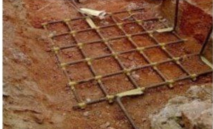
Functions:
- Protect personnel from electric shocks.
- Provide neutral earthing for transformer windings.
- Discharge overvoltages from lightning or power surges.
- Provide a discharge path for phase-to-ground faults.
- Ensure metallic structures in substations are earthed.
- Earth mat is used in 110kV/220kV substations.
- Structures like fences, tanks, towers, water pipes, etc., should be earthed.
Conclusion 🙏
At the end, earthing is one of most important part of electrical system.it is protecting your home from electrical faults or keeping big industrial setups running safely, a good earthing system is like the unsung hero behind the scenes. So next time you flip a switch or plug something in, just remember—there’s a solid connection to the ground helping keep everything safe .😎

.jpg)

Comments
Post a Comment